


jlgarce
-
Mensajes
259 -
Ingresó
-
Última visita
Tipo de contenido
Perfiles
Foros
Calendario
Tienda
Todo lo publicado por jlgarce
-
Hola a todos, tengo un teléfono Samsung Galaxy S SCL con Android 2.3.5 y el MMI 2G actualizado a la 5570. El caso es que el teléfono se conecta al coche pero al rato se desconecta y desaparece el símbolo del bluetooth en la pantalla del MMI. Lo raro es que el teléfono sigue indicando que está conectado y después de esto ya no hay manera de que vuelva a hacer una conexión real con el coche, incluso si llamas con el teléfono, no se oye al interlocutor, por lo que hay que apagar y encender el teléfono para que deje de hacer cosas raras. Lo he probado con un Parrot y va todo correctamente incluso la agenda por lo que pienso que es algún problema de compatibilidad con el MMI. Alguien puede aportar algo sobre el tema. Un saludo.
-
Si que hay una manera de saber cuales están mal, pero yo no se como se hace. Yo te aconsejo que si te metes a cambiarlos, los cambies todos. A mi en garantía primero me cambiaron dos y luego en otro taller me cambiaron todos al parecer por una nota interna de Audi. Saludos
-
Hola Tyson, la codificación es muy fácil, tienes que entrar en los canales del 71 al 76 y meter el codigo de 7 dígitos que viene en el inyector en cuestión. Te pongo el método. Injector Quantity Adjustment (IMA) and Injector Voltage Adjustment (ISA) These values represent the behavior of an injection valve (Piezo Injector). Caused by manufacturing tolerances the injectors have a unique behavior and get divided into separate classes. In combination with the automatically determined learning values of the engine control module the pre- and post-injections are being calculated individually for each valve. The behavior of an injection valve is also mileage dependent, so a valve with e.g. 10000 km has a different behavior then one with 70000 km. The control module determines these automatically while driving so the learning values change against the mileage. When altering one of the following values the learning values are being reset because the ECU thinks you are adjusting a new valve. The IMA-ISA values need to be adapted when: One or more injection valves have been replaced. Make sure not to adjust the valves which have not been changed! The engine control module has been replaced. Do NOT adapt these values when you did not replace one of the above parts, also not for training or demonstration purposes. The adjustment code can be found on the injector itself, it is a 7-digit value and does only use the following chars: 1,2,3,4,5,6,7,8,A,B,C,D,E,F,G,H,K,L,M,N,O,P,R,S,T,U,V,W,X,Y,Z. A value of AAAAAAA is also not valid. Prerequisites: Ignition ON Engine OFF [select] [01 - Engine] [Adaptation - 10] Channel 071: IMA-ISA Value for Cylinder 1 Channel 072: IMA-ISA Value for Cylinder 2 Channel 073: IMA-ISA Value for Cylinder 3 Channel 074: IMA-ISA Value for Cylinder 4 Channel 075: IMA-ISA Value for Cylinder 5 Channel 076: IMA-ISA Value for Cylinder 6 Un Saludo.
-
+CONSUMO DESPUES LIMPIEZA CAJA MARIPOSA y ADMISION
jlgarce responde a rmorenoh de discusión en Audi A6 / Allroad C6 (2005 - 2011)
Otra: Basic setting as at 30.10. 2008 for 2.7/3.0 L TDI CR Engine code letters: CANA, CANB, CANC, CAND, CDYA, CDYB, CDYC 001 Quantity adjustment 1) Engine speed At idle: 610 ... 810 rpm 2) Injection quantity mean At idle: 4 ... 11 mg/stroke 3) Rail pressure actual Check values with measured value block 020 4) Coolant temperature Warmed-up: 70 ... 115 °C 002 Idling speed 1) Engine speed At idle: 610 ... 810 rpm 2) Accelerator pedal position At idle: 0 % At full throttle: 100% 3) Accelerator pedal switch settings X X X X X X X 1 Status AC compressor ON X X X X 1 X X X Idling speed switch ON X X X 1 X X X X Kickdown switch ON X 1 X X X X X X Idling speed increased 4) Coolant temperature Warmed-up: 70 ... 115 °C 003 Exhaust gas recirculation EGR 1) Engine speed At idle: 610 ... 810 rpm 2) Specified intake air mass [mg/stroke] 3) Actual air mass [mg/stroke] 4) EGR control value [%] 004 Main injection 1) Engine speed At idle: 610 ... 810 rpm 2) Main injection, start of activation [°CA] 3) Main injection, duration of activation [ms] 4) Rail pressure actual Check values with measured value block 020 005 Starting conditions Stored from last engine start 1) Engine speed [rpm] 2) Starting injection quantity [mg/stroke] 3) Start synchronisation 001 No synchronisation between engine control unit and engine 005 Too many resynchronisation cycles Torsion between crankshaft and camshaft too large 020 Position for synchronisation set by run-out detector 033 Synchronisation present, but still being checked 036 Synchronisation present, but still being checked (slave engine control unit only) 038 No valid camshaft signal, run camshaft emergency mode to synchronise 048 Synchronisation complete --> Starting OK 060 No valid crankshaft signal, crankshaft emergency running mode 4) Coolant temperature [°C] 006 Cruise control system CCS 1) Vehicle speed CCS activatable: above 35 km/h 2) CCS status X X X X X X X 1 Brake light switch pressed X X X X X X 1 X Brake pedal switch pressed X X X X X 1 X X Clutch pedal switch pressed X X X X 1 X X X CCS enabled X X X 1 X X X X ACC enabled X X 1 X X X X X Main switch ON 0 0 X X X X X X ACC/CCS mode inactive 1 0 X X X X X X State overspill 0 1 X X X X X X ACC/CCS in control range 1 1 X X X X X X ACC not enabled 3) CCS target speed [km/h] 4) CCS switch settings X X X X X X X 1 Main switch ON X X X X X X 1 X Tapped OFF X X X X X 1 X X Tap Down, reduce X X X X 1 X X X Tap Up, increase X X X 1 X X X X Set X X 1 X X X X X Resume X 1 X X X X X X Fault message steering column module 1 X X X X X X X Main switch hardware locked ON 007 Temperature senders 1) Fuel temperature to 70 °C 2) Oil temperature Warmed-up: 70 ... 110 °C 3) Intake air temperature to 90 °C 4) Coolant temperature Warmed-up: 70 ... 115 °C 008 Limiting torques 1) Engine speed [rpm] 2) Engine torque specification [Nm] Driver input via accelerator pedal 3) Torque limitation [Nm] 4) Smoke limitation [Nm] 009 Limiting torques 1) Engine speed [rpm] 2) CCS limiting torque [Nm] 3) Limiting torque gearbox control unit [Nm] 4) Limiting torque [Nm] 010 Air quantities 1) Actual air mass At idle: 210 ... 280 mg/stroke At full throttle: > 1050 mg/stroke At ambient air pressure 970 ... 1020 mbar 2) Ambient air pressure [mbar] 3) Actual charge pressure At idle: 950 ... 1080 mbar At full throttle: > 2150 mbar At ambient air pressure 970 ... 1020 mbar 4) Accelerator pedal position [%] - With exhaust gas recirculation switched off, e.g. due to high intake air temperature the air mass at idle may be increased In this case press the accelerator in short bursts and check whether the air mass then decreases. - Additionally check air mass via basic setting of EGR and turbocharger basic setting. 011 Charge pressure control 1) Engine speed [rpm] 2) Specified charge pressure [mbar] 3) Actual charge pressure At idle: 950 ... 1080 mbar At full throttle: > 2150 mbar At ambient air pressure 970 ... 1020 mbar 4) Charge pressure control value [%] 012 Preheating system 1) Preheating system status 0 0 0 0 0 0 0 0 Waiting for coolant temperature 0 0 0 0 0 0 0 1 Waiting for start request 0 0 0 1 0 0 0 0 Glow period 0 1 0 1 0 0 0 0 No glow 1 0 1 1 0 0 0 0 After-glow 1 1 0 0 0 0 0 0 No start glow 1 1 1 1 0 0 0 0 Intermediate glow 0 0 1 1 0 0 0 0 Readiness glow 0 1 1 1 0 0 0 0 Start glow 1 0 1 1 0 0 0 1 Waiting for after-glow 1 1 0 1 0 0 0 0 No after-glow 1 1 1 1 0 0 0 1 Waiting for intermediate glow 1 1 1 1 1 1 1 1 No glow 2) Glow period 3)Vehicle voltage [V] 4) Coolant temperature [°C] 013 Smooth running control 1) Cylinder 1 injection quantity variation [mg/stroke] 2) Cylinder 2 injection quantity variation [mg/stroke] 3) Cylinder 3 injection quantity variation [mg/stroke] 4) Vacant Permissible values at idle: +- 1.5 mg/stroke A If the permissible tolerance is exceeded first check injector IQA-IVA adaption values, if OK electrical wiring and connectors from engine control unit to injector 014 Smooth running control 1) Cylinder 4 injection quantity variation [mg/stroke] 2) Cylinder 5 injection quantity variation [mg/stroke] 3) Cylinder 6 injection quantity variation [mg/stroke] 4) Vacant Permissible values at idle: +- 1.5 mg/stroke A If the permissible tolerance is exceeded first check injector IQA-IVA adaption values, if OK electrical wiring and connectors from engine control unit to injector 015 Fuel consumption 1) Engine speed [rpm] 2) Actual engine torque [Nm] 3) Fuel consumption [litres/h] 4) Engine torque specification [Nm] Driver input via accelerator pedal 016 Additional heater Only A4, A5, A6 1) Additional heater enable 0 0 No enable 0 1 No enable stage 1 1 0 No enable stage 2 1 1 Enable stages 1 and 2 2) Additional heater shut-off conditions X X X X X X X 0 No shut-off condition X X X X X X X 1 Coolant temperature adequate X X X X X X 1 X Alternator load signal fault X X X X X 1 X X Battery voltage too high X X X X 1 X X X Engine speed too low X X X 1 X X X X Start delay active X X 1 X X X X X Water temperature sensor, air temperature sensor or output stage defective X 1 X X X X X X Operating switch (not active) 1 X X X X X X X Intake manifold temperature adequate 3) Additional heater relay activation 0 0 Relay not activated 0 1 Low heat output relay 1 0 High heat output relay 1 1 Both relay contacts active 4) Alternator output 017 --- For readiness code see 089 018 Rail pressure control 1) Engine speed [rpm] 2) Fuel temperature [°C] 3) Rail pressure control status 00 Ignition on, open-loop control mode 01 Open-loop control mode after start 02 Closed-loop control via pressure regulating valve (on switch between open-loop and closed-loop control) 03 Closed-loop control via solenoid valve (on switch between open-loop and closed-loop control) 04 Closed-loop control via pressure regulating valve (normal operating mode) 05 Closed-loop control via solenoid valve (normal operating mode) 06 Closed-loop control via pressure regulating valve (on switch to pressure regulation via quantity control valve) 07 Open-loop control (engine is stopped) 08 Open-loop control (on switch from open-loop to closed-loop control) 11 Open-loop control after running tank empty 15 Closed-loop control via pressure regulating valve and quantity control valve 16 Switch after closed-loop control via pressure regulating valve to quantity control valve 17 Switch after CPC closed-loop control 18 Switch after closed-loop control via quantity control valve 4) Vacant 020 Rail pressure control 1) Engine speed At idle: 610 ... 810 rpm 2) Specified rail pressure [bar] 3) Rail pressure actual [bar] 4) Pressure regulating valve activation At idle: 13 ... 37 % - Values for warmed-up engine - Permissible difference between specified and actual value at Idle: maximum +-20 bar 021 Rail quantity control 1) Engine speed At idle: 610 ... 810 rpm 2) Specified rail pressure Check values with measured value block 020 3) Rail pressure actual Check values with measured value block 020 4) Quantity adjuster valve activation At idle: 33 ... 62 % - Values for warmed-up engine 024 Pre-injection 3 1) Engine speed [rpm] 2) Pre-injection 3 start of activation [°CA] 3) Pre-injection 3 duration of activation [ms] 4) Rail pressure actual Check values with measured value block 020 025 Pre-injection 2 1) Engine speed [rpm] 2) Pre-injection 2 start of activation [°CA] 3) Pre-injection 2 duration of activation [ms] 4) Rail pressure actual Check values with measured value block 020 026 Pre-injection 1 1) Engine speed [rpm] 2) Pre-injection 1 start of activation [°CA] 3) Pre-injection 1 duration of activation [ms] 4) Rail pressure actual Check values with measured value block 020 028 Post-injection 2 1) Engine speed [rpm] 2) Post-injection 2 start of activation [°CA] 3) Post-injection 2 duration of activation [ms] 4) Rail pressure actual Check values with measured value block 020 029 Post-injection 1 1) Engine speed [rpm] 2) Post-injection 1 start of activation [°CA] 3) Post-injection 1 duration of activation [ms] 4) Rail pressure actual Check values with measured value block 020 030 Accelerator pedal position 1) Accelerator pedal sender 1 [V] 2) Accelerator pedal sender 2 [V] 3) Accelerator pedal switch settings X X X X X X X 1 Status AC compressor ON X X X X 1 X X X Idling speed switch ON X X X 1 X X X X Kickdown switch ON X 1 X X X X X X Idling speed increased 4) Accelerator pedal position [%] 032 Camshaft edges 1) Engine speed [rpm] 2) Start synchronisation 001 No synchronisation between engine control unit and engine 005 Too many resynchronisation cycles Torsion between crankshaft and camshaft too large 020 Position for synchronisation set by run-out detector 033 Synchronisation present, but still being checked 036 Synchronisation present, but still being checked (slave engine control unit only) 038 No valid camshaft signal, run camshaft emergency mode to synchronise 048 Synchronisation complete --> Starting OK 060 No valid crankshaft signal, crankshaft emergency running mode 3) Camshaft edge 1 [°CA] 4) Camshaft edge 2 [°CA] 033 Temperature protection Only 3.0 L TDI CR 1) Engine speed At idle: 610 ... 810 rpm 2) Exhaust gas temperature before turbocharger At idle: 100 ... 310 °C (with radiator fluid > 75 °C) At full throttle: 540 ... 830 °C 3) Exhaust gas temperature governing factor At idle: 99 ... 101 % or 0.99 ... 1,01 4) Overall governing factor At idle: 99 ... 101 % or 0.99 ... 1,01 034 Charge pressure control 1) Engine speed At idle: 610 ... 810 rpm 2) Charge pressure adjuster activation [%] 3) Charge pressure adjuster feedback [%] 4) Charge pressure adjuster output stage [%] Permissible difference between activation and feedback at Idle: maximum +/- 2 % 036 Intake manifold flap bank 1 1) Engine speed At idle: 610 ... 810 rpm 2) Intake manifold flaps activation [%] 3) Intake manifold flaps feedback [%] 4) Intake manifold flaps output stage [%] Permissible difference between activation and feedback at Idle: maximum +/- 2 % 037 Intake manifold flap bank 2 1) Engine speed At idle: 610 ... 810 rpm 2) Intake manifold flaps 2 activation [%] 3) Intake manifold flaps 2 feedback [%] 4) Intake manifold flaps 2 output stage [%] Permissible difference between activation and feedback at Idle: maximum +/- 2 % 038 EGR valve 1) Engine speed [rpm] 2) EGR valve activation [%] 3) EGR valve feedback [%] 4) EGR valve output stage [%] 040 Throttle valve 1) Engine speed [rpm] 2) Throttle valve activation [%] 3) Throttle valve feedback [%] 4) Throttle valve output stage [%] 041 Lambda probe 1) Lambda probe calibration value internal resistance [Ohm] 2) Oxygen signal offset [V] 3) Oxygen concentration [%] 4) Oxygen signal calibration status 0 inactive 1 active 042 Lambda probe 1) Air mass throughput [-] 2) Lambda probe heater activation [%] 3) Lambda probe temperature signal [V] 4) Lambda signal [-] 043 Lambda probe 1) Air mass throughput [-] 2) Ambient temperature [°C] 3) Lambda probe pressure [mbar] 4) Lambda probe oxygen concentration [mV] 044 Lambda probe 1) Engine speed [rpm] 2) Lambda probe electronics X X X X X X X 1 Full throttle regulator on/off X X X X X X 1 X Full throttle X X X X X 1 X X Control deviation negative, i.e. mixture too rich X X X X 1 X X X System fault X X X 1 X X X X Oxygen signal invalid or no correction by lambda probe adaption X X 1 X X X X X Engine starting X 1 X X X X X X Torque limitation or quantity limitation active 1 X X X X X X X Regeneration exhaust gas treatment 3) Lambda probe plausibility check 001 Current oxygen concentration implausibly high 002 Current oxygen concentration implausibly low 004 Oxygen concentration stationary 008 Plausibility checking enabled 016 Oxygen concentration zero 032 In last time interval no rich operation 4) Lambda probe diagnosis 004 Dynamics of signal too low 008 Cable open circuit 016 Oxygen signal in overrun implausibly low 032 Oxygen signal in overrun implausibly high 064 Oxygen signal at part throttle implausibly low 128 Oxygen signal at part throttle implausibly high 256 Oxygen signal at full throttle implausibly low 512 Oxygen signal at full throttle implausibly high 045 Fan activation 1) Coolant temperature [°C] 2) Air conditioner fan activation [%] 3) Radiator fan 1 activation [%] 4) Radiator fan 2 activation [%] 046 AC compressor 1) Ambient temperature [°C] 2) Temperature at air conditioner heat exchanger output [°C] 3) AC compressor shut-off status 1 X X X X X X X 1 Vehicle starting off X X X X X X 1 X Shut-off due to starting off state X X X X X 1 X X Vehicle acceleration status X X X X 1 X X X Shut-off due to acceleration X X X 1 X X X X Shut-off due to starting X X 1 X X X X X System fault detected X 1 X X X X X X Shut-off due to system fault 1 X X X X X X X Shut-off due to inadequate idling speed 4) AC compressor shut-off status 2 0 Compressor not switched off by control unit 1 Compressor switched off by control unit 051 Speed recording 1) Engine speed [rpm] 2) Camshaft speed [rpm] 3) Start synchronisation 001 No synchronisation between engine control unit and engine 005 Too many resynchronisation cycles Torsion between crankshaft and camshaft too large 020 Position for synchronisation set by run-out detector 033 Synchronisation present, but still being checked 036 Synchronisation present, but still being checked (slave engine control unit only) 038 No valid camshaft signal, run camshaft emergency mode to synchronise 048 Synchronisation complete --> Starting OK 060 No valid crankshaft signal, crankshaft emergency running mode 4) Vacant 057 Engine mounting 1) Engine speed [rpm] 2) Vehicle speed [km/h] 3) Engine mounting valve, right, activation [%] 4) Engine mounting valve, left, activation [%] 059 Ancillaries 1) Engine speed [rpm] 2) Actual engine torque [Nm] 3) Engine torque loss [Nm] 4) Ancillaries torque [Nm] 060 Ancillaries 1) Engine torque loss [Nm] 2) Clutch torque min [Nm] 3) AC compressor torque [Nm] 4) Alternator output [W] 070 Zero quantity calibration ZQC 1) ZQC learning cycle counter 1st calibration pressure [-] 2) ZQC learning cycle counter 2nd calibration pressure [-] 3) ZQC learning cycle counter 3rd calibration pressure [-] 4) Vacant 072 Zero quantity calibration ZQC 1) ZQC cyl. 1 Activation time 1st calibration pressure [ms] 2) ZQC cyl. 1 Activation time 2nd calibration pressure [ms] 3) ZQC cyl. 1 Activation time 3rd calibration pressure [ms] 4) Vacant 073 Zero quantity calibration ZQC 1) ZQC cyl. 2 Activation time 1st calibration pressure [ms] 2) ZQC cyl. 2 Activation time 2nd calibration pressure [ms] 3) ZQC cyl. 2 Activation time 3rd calibration pressure [ms] 4) Vacant 074 Zero quantity calibration ZQC 1) ZQC cyl. 3 Activation time 1st calibration pressure [ms] 2) ZQC cyl. 3 Activation time 2nd calibration pressure [ms] 3) ZQC cyl. 3 Activation time 3rd calibration pressure [ms] 4) Vacant 075 Zero quantity calibration ZQC 1) ZQC cyl. 4 Activation time 1st calibration pressure [ms] 2) ZQC cyl. 4 Activation time 2nd calibration pressure [ms] 3) ZQC cyl. 4 Activation time 3rd calibration pressure [ms] 4) Vacant 076 Zero quantity calibration ZQC 1) ZQC cyl. 5 Activation time 1st calibration pressure [ms] 2) ZQC cyl. 5 Activation time 2nd calibration pressure [ms] 3) ZQC cyl. 5 Activation time 3rd calibration pressure [ms] 4) Vacant 077 Zero quantity calibration ZQC 1) ZQC cyl. 6 Activation time 1st calibration pressure [ms] 2) ZQC cyl. 6 Activation time 2nd calibration pressure [ms] 3) ZQC cyl. 6 Activation time 3rd calibration pressure [ms] 4) Vacant 089 Readiness code 1) EOBD data A X 0 0 0 0 0 0 0 No fault messages stored in engine control unit 0 X X X X X X X Emissions warning lamp (MIL) OFF 1 X X X X X X X Emissions warning lamp (MIL) ON 2) EOBD data B - X X X - X X 1 Misfire monitoring activated - X X X - X 1 X Fuel system monitoring activated - X X X - 1 X X Complete system monitoring activated - X X X - 1 X X Misfire detection monitoring activated - X 0 X - X X X EOBD test fuel system completed with OK - 0 X X - X X X EOBD test overall system completed with OK 3) EOBD data C X X X X X X X 1 Catalytic converter monitoring activated X X X X X X 1 X Catalytic converter hot monitoring activated X X X X X 1 X X Evaporation system monitoring activated X X X X 1 X X X Secondary air system monitoring activated X X X 1 X X X X Air conditioner coolant monitoring activated X X 1 X X X X X Lambda probe monitoring activated X 1 X X X X X X Lambda probe heating monitoring activated 1 X X X X X X X EGR monitoring activated 4) EOBD data D X - - - - - - 0 EOBD test EGR completed with OK 0 - - - - - - X EOBD test EGR completed with OK 095 Starter control 1) Start request terminal 50 X X 1 Start request from driver X 1 X Holding circuit to bridge resets active 1 X X Read-back activation status of starter 2) Interlock or P/N signal Interlock: Signal from selector lever switch Only vehicles with automatic gearbox P/N: Signal from clutch pedal switch for engine start Only vehicles with manual gearbox X X X X X X X 1 Clutch closed X X X 1 X X X X Interlock or P/N signal 3) Starter control status 1 X X X X X X X 1 Start command X X X X X X 1 X Engine does not turn over X X X X X 1 X X Starter motor does not turn over X X X X 1 X X X Power enable X X X 1 X X X X Restart enable X X 1 X X X X X Start command from start/stop coordinator X 1 X X X X X X Engine speed permitted, engage starter 1 X X X X X X X Start mode announcement 4) Starter control status 2 X X X X X X X 1 Start delay active 096 Starter control 1) Start request terminal 50 X X 1 Start request from driver X 1 X Holding circuit to bridge resets active 1 X X Read-back activation status of starter 2) Starter control shut-off conditions 1 X X X X X X X 1 New fault in starter control X X X X X X 1 X Start by term. 15 off X X X X X 1 X X Fast start (direct start) 3) Starter control shut-off conditions 2 X X X X X X X 1 Start rejection speed reached X X X X X X 1 X Engine speed reached and term.50 off X X X X X 1 X X Maximum operating time exceeded X X X X 1 X X X Term.50 off after number of time false starts X X X 1 X X X X Abort panic start X X 1 X X X X X Power detected X 1 X X X X X X Vehicle speed exceeded 1 X X X X X X X Abort semi-automatic start 4)Vehicle voltage [V] 098 EGR cooler coolant pump 1) Coolant temperature [°C] 2) Coolant temperature at radiator outlet [°C] 3) EGR cooler coolant pump, activation [%] 4) EGR temperature [°C] 099 Exhaust gas temperature 1) Engine speed [rpm] 2) Exhaust gas temperature before turbocharger [°C] 3) Exhaust gas temperature before particulate filter [°C] 4) Exhaust gas temperature before particulate filter [°C] Only on vehicles with particulate filter The temperature sender is not fitted on the Q7. The readout is calculated. 100 Service regeneration Only on vehicles with particulate filter Note: Starting service regeneration is possible via Guided Fault Finding if the <service regeneration> test procedure was entered in the test plan. 1) Engine speed In service regeneration: approx. 1500 rpm 2) Surface temperature of filter [°C] 3) Service regeneration current regeneration time 0 ... 255 or 0 to max. 1200 s Total duration: 10 to 40 minutes, depending on loading state 4) Service regeneration abort detected 0 = Not aborted 1 = Aborted 101 Service regeneration Only on vehicles with particulate filter Note: With this measured value block fault causes can be located if the service regeneration was aborted by the engine control unit 1) Service regeneration enable conditions 1 Before start of service regeneration: 0 0 0 0 0 0 0 0 OK, because no service regeneration active After start of service regeneration: 1 1 1 1 1 1 1 1 All enable conditions 1 OK X X X X X X X 1 Minimum waiting time before start of service regeneration with engine running observed X X X X X X 1 X Coolant temperature OK X X X X X 1 X X Oil temperature OK X X X X 1 X X X Ambient air pressure OK X X X 1 X X X X Fuel temperature OK X X 1 X X X X X Battery voltage OK X 1 X X X X X X No clutch pressed 1 X X X X X X X No gear engaged 2) Service regeneration enable conditions 2 Before start of service regeneration: 0 0 0 0 0 0 0 0 OK, because no service regeneration active After start of service regeneration: 1 1 1 1 1 1 1 1 All enable conditions 2 OK X X X X X X X 1 Road speed = 0 X X X X X X 1 X Engine speed OK X X X X X 1 X X Injection quantity OK X X X X 1 X X X Accelerator pedal not pressed X X X 1 X X X X Particulate filter temperature bank 1 OK X X 1 X X X X X Particulate filter temperature bank 2 OK X 1 X X X X X X Pre-catalyst temperature bank 1 OK 1 X X X X X X X Pre-catalyst temperature bank 2 OK 3) Service regeneration enable conditions 3 Before start of service regeneration: 0 0 0 0 0 0 0 0 OK, because no service regeneration active After start of service regeneration: 1 1 1 1 1 1 1 1 All enable conditions 3 OK X X X X X X X 1 Soot mass in particulate filter in permissible Range X X X X X X 1 X No faults in particulate filter functions X X X X X 1 X X No faults in engine functions X X X X 1 X X X Maximum regeneration time not exceeded --> If not OK: Consumers not switched on, ambient temperature too cold X X X 1 X X X X Exhaust gas system heat-up time bank 1 within permissible limits --> If not OK: Consumers not switched on, ambient temperature too cold X X 1 X X X X X Exhaust gas system heat-up time bank 2 within permissible limits --> If not OK: Consumers not switched on, ambient temperature too cold X 1 X X X X X X Maximum temperature before particulate filter bank 1 not exceeded 1 X X X X X X X Maximum temperature before particulate filter bank 2 not exceeded 4) Service regeneration phase X X X X X X X 1 Normal operation X X X X X X 1 X Start X X X X X 1 X X Heat-up 1 X X X X 1 X X X Heat-up 2 X X X 1 X X X X Regeneration X X 1 X X X X X Cool-down X 1 X X X X X X Regeneration successful 1 X X X X X X X Regeneration active 102 Exhaust gas cleaning Only on vehicles with particulate filter 1) Exhaust gas temperature after pre-catalyst A5, B8, Q5, C6 [°C] 2) Vacant 3) Particulate filter differential pressure 0 ... 950 mbar 4) Differential pressure offset particulate filter [mbar] 103 Field regeneration Only on vehicles with particulate filter 1) Field regeneration status 1 X X X X X X X 1 Normal operation X X X X X X 1 X Regeneration mode 2) Field regeneration status 2 X X X 1 X X X X Normal operation X X X 1 X X 1 X Regeneration mode 3) Field regeneration request X X 1 Request by fuel consumption X 1 X Request by operating time 1 X X Request by distance driven 4) Field regeneration block 0 Regeneration disabled 1 Maximum regeneration time elapsed 104 Particulate filter Only on vehicles with particulate filter 1) Oil ash [Ltr] 2) Soot mass calculated [g] 3) Soot mass measured [g] 4) Distance since last regeneration [km] 107 Particulate filter Only on vehicles with particulate filter 1) Loading limit 4 [g] - Value depends on software version and fitted Particulate filter - If the soot mass ("calculated" or "measured", se measured value block 104, zone 2 or 3) exceeds this limit, field and service regeneration is disabled. - If after a test drive (approx. 20 minutes at > 2500 rpm) one of the soot mass values is still higher than load limit 4, the particulate filter must be replaced. 2) Loading limit 3 [g] - Value depends on software version and fitted Particulate filter - If this limit is exceeded, the engine switches to emergency running and the fault memory entry "Particulate filter overloaded" is stored 3) Loading limit 1 [g] - Value depends on software version and fitted Particulate filter - If this limit is exceeded, an attempt is made to start field regeneration (during driving) 4) Exhaust gas volumetric flow particulate filter [m^3/h] Calculated value 110 Adaptive cruise control ACC 1) ACC specification adjustment 001 Specification adjustment free-wheeling 002 Specification adjustment ON 003 Specification adjustment OFF 2) ACC status X X X X X X 0 0 ACC inactive X X X X X X 0 1 ACC active X X X X X X 1 0 ACC passive X X X X X X 1 1 ACC initialisation X X X X X 0 X X No neutral value X X X X X 1 X X Neutral value X X 0 X X X X X Not permitted X X 1 X X X X X Permitted 3) Vehicle speed [km/h] 4) Vacant 125 CAN communication 1) CAN communic. Automatic gearbox 2) CAN communic. ABS/ESP 3) CAN communic. Instrument cluster 4) CAN communic. Airbag 0 = inactive 1 = active 126 CAN communication 1) CAN communic. AC 2) Vacant 3) Vacant 4) CAN communic. ACC 0 = inactive 1 = active 127 CAN communication 1) CAN communic. 4WD 2) CAN communic. Level 3) CAN communic. Drive authorisation 4) CAN communic. Steering column module 0 = inactive 1 = active 128 CAN communication 1) CAN communic. Gateway 2) CAN communic. Battery energy management 3) CAN communic. Steering angle sender 4) CAN communic. Parking brake 0 = inactive 1 = active CAN = Controller Area Network The CAN bus is a network for local interconnection of control units. 202 Oil pressure pump 1) Engine speed [rpm] 2) Control oil pump activation 3) Oil low-pressure switch active 4) Oil high-pressure switch active -
+CONSUMO DESPUES LIMPIEZA CAJA MARIPOSA y ADMISION
jlgarce responde a rmorenoh de discusión en Audi A6 / Allroad C6 (2005 - 2011)
Otra cosa que encontré y creo que es la buena auque no aparece el motor BMK Basic setting for 2.7 L and 3.0 L TDI CR as at 30.10. 2008 Engine code letters: CANA, CANB, CANC, CAND, CDYA, CDYB, CDYC KNote: To start the "Basic setting" function from Guided Fault Finding: 1) Press mode button 2) Choose "Vehicle self-diagnosis" menu option 3) Self-diagnosis 003 Basic setting: Exhaust gas recirculation 1) Coolant temperature at least 80 °C 2) Switch off ignition briefly, then start engine 3) Start basic setting 4) Follow driver instructions (pedals must be pressed) 5) Wait for the engine speed rise to approx. 1000 rpm KNote: The exhaust gas recirculation is now switched on and off intermittently. Specifications with "EGR not active": Engine speed: approx. 1000 rpm Activation: EGR not active Actual air mass: 380 ... 550 mg/stroke EGR valve feedback: 0 ... 2 % Specifications with "EGR active": Engine speed: approx. 1000 rpm Activation: EGR active Actual air mass: 140 ... 270 mg/stroke EGR valve feedback: 80 ... 100 % 033 Basic setting: Turbocharger 1) Coolant temperature at least 80 °C 2) Switch off ignition briefly, then start engine 3) Start basic setting 4) Follow driver instructions (pedals must be pressed) 5) Wait for the engine speed rise to approx. 1000 rpm KNote: The turbocharger is now activated at intervals at different duty cycles. Specifications at "closed": Engine speed: approx. 1000 rpm Activation: closed Actual charge pressure: 970 ... 1150 mbar Charge pressure adjuster feedback: 98 ... 100 % Specifications at "open": Engine speed: approx. 1000 rpm Activation: open Actual charge pressure: 910 ... 1050 mbar Charge pressure adjuster feedback: 0 ... 2 % Charge pressure difference between "closed/open": 50 ... 135 mbar OK is OK 044 Basic setting: Intake manifold flap bank 1 1) Coolant temperature at least 80 °C 2) Switch off ignition briefly, then start engine 3) Start basic setting 4) Follow driver instructions (pedals must be pressed) 5) Wait for the engine speed rise to approx. 2800 rpm KNote: The bank 1 intake manifold flaps are now alternately opened and closed at intervals. Specifications with "flap open": Engine speed: approx. 2800 rpm Activation: Flap open Actual air mass: [mg/stroke] Intake manifold flap bank 1 feedback: 3 ... 7 % Specifications with "flap closed": Engine speed: approx. 2800 rpm Activation: Flap closed Actual air mass: [mg/stroke] Intake manifold flap bank 1 feedback: 93 ... 97 % Air mass difference between "flap open/closed": min. 20 mg/stroke 055 Basic setting: Intake manifold flap bank 2 1) Coolant temperature at least 80 °C 2) Switch off ignition briefly, then start engine 3) Start basic setting 4) Follow driver instructions (pedals must be pressed) 5) Wait for the engine speed rise to approx. 2800 rpm KNote: The bank 2 intake manifold flaps are now alternately opened and closed at intervals. Specifications with "flap open": Engine speed: approx. 2800 rpm Activation: Flap open Actual air mass: [mg/stroke] Intake manifold flap bank 2 feedback: 3 ... 7 % Specifications with "flap closed": Engine speed: approx. 2800 rpm Activation: Flap closed Actual air mass: [mg/stroke] Intake manifold flap bank 2 feedback: 93 ... 97 % Air mass difference between "flap open/closed": min. 20 mg/stroke 063 Adapting kickdown point Not AUDI A8 Only vehicles with automatic gearbox 1) Switch off ignition briefly, then ignition on 2) Start basic setting 3) Press down accelerator pedal until status ADP OK is displayed 4) Value is only stored in engine control unit after approx. 10 seconds ignition OFF. Specifications: Sender 1 Accelerator position: 12 ... 97 % --- Status: ADP.OK 159 Basic setting: Oil pressure valve 1) Engine oil temperature at least 60 °C 2) Switch off ignition briefly, then start engine 3) Start basic setting 4) Follow driver instructions (pedals must be pressed) KNote: First the low pressure stage is run for 8 seconds. During this time the engine speed is increased to 2300 rpm. Then the system switches to the high pressure stage, which is likewise active for 8 seconds. Specifications in the low pressure stage: Oil pressure switching valve: 1(low pressure requested) Low-pressure switch: 1(closed) High-pressure switch: 0(open) Specifications in the high pressure stage: Oil pressure switching valve: 0(high pressure requested) Low-pressure switch: 1(closed) High-pressure switch: 1(closed) Saludos -
+CONSUMO DESPUES LIMPIEZA CAJA MARIPOSA y ADMISION
jlgarce responde a rmorenoh de discusión en Audi A6 / Allroad C6 (2005 - 2011)
Hola a todos, creo que no habláis de las mismas mariposas, el motor 3,0 TDI tiene una 1ª válvula de mariposa que es la que da entrada de aire a los dos colectores de admisión y una válvula de mariposa por cada cilindro llamada mariposa de turbulencia espiroidal (6 válvulas). Cada bancada de cilindros lleva tres de estas mariposas y las tres son comandadas a la vez por un servomotor que es el que hay que adaptar con el ajuste básico. Podéis ver de lo que hablo en este enlace: http://www.audisport-iberica.com/ftp_asi/Descargas/A64F/Manual_A64F_Grupos_mecanicos.pdf Yo presencié el ajuste básico de mi coche en Audi, ya que después de una reparación notaba lo que comentáis en cuanto a consumos y potencia del motor. El ajuste básico lo hicieron a estos servos, a la válvula de by-pass del turbo y a la EGR. La máquina VAS de Audi le decía al técnico que tenía que hacer y me llamó la atención que a veces pedía pisar el freno. Llevo bastante tiempo buscando como hacer todo el ajuste básico y no he encontrado nada salvo esto que pongo de en un foro ruso y que no estoy seguro si es para este coche. Espero que a partir de esto alguien pueda aportar algo más. Por otra parte lo que si que ocurre es que a pesar de no hacer el ajuste básico, el coche va adaptando parámetros sólo y con el tiempo las prestaciones y el consumo mejoran. Ahí va el foro ruso: Прежде всего огомное спасибо GOL_AUTO Маленькая посказка про педаль тормаза и полный газ и все заработало единственное в моем источнике нет ничего про упомянутый тобой 28 канал Вообщем сейчас у меня все 00000000 Я думаю будет полезно для всех кому это интересно указать еще на одну мелочь что все адаптации достатчно длительные по времени от минуты до 3 или даже 4 и в заключении темы было бы полезно выложить в помощь остальным порядок настройки , что я и сделаю она есть в интернете но долго искать, кстати на этом форуме я не нашел так, что пусть бует. Еще раз спасибо Manually Generating Readiness Ignition ON and Engine OFF Reading and clearing fault codes [select] [01 - Engine] [Fault Codes - 02] [Clear Codes -05] [Done, Go Back] Throttle Body Alignment [Measuring Blocks - 08] Select group 060 [Go] [switch to basic settings] Once you do this you will see the top right display say ADP RUN. Leave it in Basic Settings until the fourth field reads ADP OK. [switch to Meas. Blocks] Transmission kickdown (applies to Auto Trans vehicles only!) Select group 063 [Go] [switch to basic settings] Once you do this you will see the top right display say ADP RUN. Leave it in Basic Settings until the fourth field reads ADP OK. [switch to Meas. Blocks] [Done, Go Back] [Close Controller, Go Back] Ignition ON and Engine ON at idle Fuel leakage test [select] [01 - Engine] [Measuring Blocks - 08] Select group 071 [Go] [switch to basic settings] Leave it in Basic Settings until the fourth field reads Syst.OK [switch to Meas. Blocks] Evap purge test Select group 070 [Go] [switch to basic settings] Leave it in Basic Settings until the fourth field reads EVAP OK [switch to Meas. Blocks] A/F control test Select group 107 [Go] [switch to basic settings] Leave it in Basic Settings until the fourth field reads Syst.OK [switch to Meas. Blocks] Ignition ON and Engine ON between 1800 and 2200 rpm O2 sensor heater test Select group 041 [Go] [switch to basic settings] Leave it in Basic Settings until there are kOhm readings in the first and third fields [switch to Meas. Blocks] Select group 042 [Go] [switch to basic settings] Leave it in Basic Settings until there are kOhm readings in the first and third fields [switch to Meas. Blocks] Ignition ON and Engine ON at idle Post-cat O2 sensors readiness test Select group 036 [Go] [switch to basic settings] Leave it in Basic Settings until you see B1-S2 OK in the first field and B2-S2 OK in the third field [switch to Meas. Blocks] Ignition ON and Engine ON between 1520 and 2280 rpm Pre-cat O2 sensors response time test Select group 034 [Go] [switch to basic settings] Leave it in Basic Settings until the fourth field reads B1-S1 OK [switch to Meas. Blocks] Select group 035 [Go] [switch to basic settings] Leave it in Basic Settings until the fourth field reads B2-S1 OK [switch to Meas. Blocks] Ignition ON and Engine ON at idle O2 sensor control test Select group 037 [Go] [switch to basic settings] Leave it in Basic Settings until the fourth field reads Syst. OK [switch to Meas. Blocks] Select group 038 [Go] [switch to basic settings] Leave it in Basic Settings until the fourth field reads Syst. OK [switch to Meas. Blocks] Post-cat O2 sensor aging test Select group 043 [Go] [switch to basic settings] Leave it in Basic Settings until the fourth field reads B1-S2 OK [switch to Meas. Blocks] Select group 044 [Go] [switch to basic settings] Leave it in Basic Settings until the fourth field reads B2-S2 OK [switch to Meas. Blocks] Ignition ON and Engine ON between 1880 and 2280 rpm Catalytic converter test Select group 046 [Go] [switch to basic settings] Leave it in Basic Settings until the fourth field reads CAT B1 OK [switch to Meas. Blocks] Select group 047 [Go] [switch to basic settings] Leave it in Basic Settings until the fourth field reads CAT B2 OK [switch to Meas. Blocks] Ignition ON and Engine ON at idle Secondary air injection test (applies to Auto Trans vehicles only!) Select group 077 [Go] [switch to basic settings] Leave it in Basic Settings until the fourth field reads Syst. OK [switch to Meas. Blocks] Select group 078 [Go] [switch to basic settings] Leave it in Basic Settings until the fourth field reads Syst. OK [switch to Meas. Blocks] [Done, Go Back] Checking Readiness [Readiness] Make sure none of the fields say Failed or Incomplete [Done, Go Back] [Close Controller, Go Back] Prerequisites: Ignition ON Engine ON System voltage at least 11.0 V. [select] [01 - Engine] [basic Settings - 04] Group 103 [Go!] Activate the Basic Setting. [ON/OFF/Next] Wait until Field 4 shows "ADP. O.K.". [Done, Go Back] [Close Controller, Go Back - 06] Switch Ignition OFF. [edit] Intake Manifold Runner Prerequisites: Ignition ON Engine OFF System voltage at least 11.0 V. [select] [01 - Engine] [basic Settings - 04] Group 142 [Go!] Activate the Basic Setting. [ON/OFF/Next] Wait until Field 4 shows "ADP. O.K.". [Done, Go Back] [Close Controller, Go Back - 06] Switch Ignition OFF for at least 60 seconds. [edit] Readiness [select] [01 - Engine] [basic Settings - 04] Group 200 [Go!] Activate the Basic Setting. [ON/OFF/Next] Firmly press Brake Pedal and Throttle Pedal (Full Throttle) at once to activate the basic setting. Field 1 shows the steps counter, which counts down to 0 - then setting readiness is done. Stay on the pedals as long as the procedure lasts. [Done, Go Back] [Close Controller, Go Back - 06] [edit] Special Functions [edit] Saludos. -
Hola a todos, alguien me puede enviar el enlace. Por cierto ¿que versión de cartografia os sale cuando le dais a la opción de "version" en el menu de navegación. Gracias y un saludo
-
Reprogramacion Inyectores!!!!
jlgarce responde a CIVIC de discusión en Audi A6 / Allroad C6 (2005 - 2011)
Creo que te han informado mal, cada inyector tiene varios números grabados que hay que introducir en la centralita. Te dejo el procedimiento de calibracion con vag-com. Es importante que lo hagas cuanto antes ya que en el momento que guardas los datos en la centralita, esta interpreta que los inyectores son nuevos y en función del tiempo que tienen estos modifica parámetros de inyección. A mi me cambiaron los inyectores en garantía y se equivocaron al meter uno de los números, cosa que comprobé con el vag-com porque me imaginaba que algo harían mal como siempre. Injector Quantity Adjustment (IMA) and Injector Voltage Adjustment (ISA) These values represent the behavior of an injection valve (Piezo Injector). Caused by manufacturing tolerances the injectors have a unique behavior and get divided into separate classes. In combination with the automatically determined learning values of the engine control module the pre- and post-injections are being calculated individually for each valve. The behavior of an injection valve is also mileage dependent, so a valve with e.g. 10000 km has a different behavior then one with 70000 km. The control module determines these automatically while driving so the learning values change against the mileage. When altering one of the following values the learning values are being reset because the ECU thinks you are adjusting a new valve. The IMA-ISA values need to be adapted when: • One or more injection valves have been replaced. Make sure not to adjust the valves which have not been changed! • The engine control module has been replaced. • Do NOT adapt these values when you did not replace one of the above parts, also not for training or demonstration purposes. The adjustment code can be found on the injector itself, it is a 7-digit value and does only use the following chars: 1,2,3,4,5,6,7,8,A,B,C,D,E,F,G,H,K,L,M,N,O,P,R,S,T,U,V,W,X,Y,Z. A value of AAAAAAA is also not valid. Prerequisites: • Ignition ON • Engine OFF [select] [01 - Engine] [Adaptation - 10] Channel 071: IMA-ISA Value for Cylinder 1 Channel 072: IMA-ISA Value for Cylinder 2 Channel 073: IMA-ISA Value for Cylinder 3 Channel 074: IMA-ISA Value for Cylinder 4 Channel 075: IMA-ISA Value for Cylinder 5 Channel 076: IMA-ISA Value for Cylinder 6 [Test] [save] [Done, Go Back] • Switch Ignition OFF, wait 10 seconds and switch Ignition ON again. The values should be saved now, please verify them by double checking the adaptation values. Espero que lo soluciones. Un saludo. -
MIS LIMPIAS ESTAN LOCOS
jlgarce responde a navarrico de discusión en Audi A6 / Allroad C6 (2005 - 2011)
Mas de lo mismo, también me funciona mal desde el principio, a veces cuando llueve fino no salta hasta que no se ve prácticamente nada por lo que tengo que darle en manual, otras veces empieza a moverse muy rápido sin razón. Esto lo he comentado varias veces en el concesionario y ni caso. Saludos -
pregunta a los a6 reprogramados
jlgarce responde a carlosax3 de discusión en Audi A6 / Allroad C6 (2005 - 2011)
Mira en la página anterior. Saludos -
pregunta a los a6 reprogramados
jlgarce responde a carlosax3 de discusión en Audi A6 / Allroad C6 (2005 - 2011)
Mira esto: http://www.audisport-iberica.com/foro/inde...p;#entry2211478 A día de hoy el coche va muy bien y estoy pendiente de hacer un hueco para llevarlo a otro banco y confirmar la ganancia en baja, pero la sensación es bastante buena. Para mi si que merece la pena y aún pisándole en un viaje largo la disminución de consumo está entre 0,3-0,5 litros Saludos. -
Necesitas bajarte e instalar de la página de NOKIA el programa Nokia_616_Contacts_Download_S60_3rd.sis. Una vez instalado ejecuta el programa y despues de esperar varios minutos (depende de lo larga que sea la agenda), podrás ver los contactos en el MMI. Un saludo
-
vibracion de embrague a6 2.0 TDI
jlgarce responde a carnacas de discusión en Audi A6 / Allroad C6 (2005 - 2011)
Ojo, el mío es un 3.0 TDI que lleva el mismo enbrague que el 2.7 TDI. Mira también la referencia de los volante bimasa ya que creo que en algún momento Audi, cambió el volante en los 2.0 TDI. En cuanto a mi coche a día de hoy no he vuelto a tener problemas, incluso castigando el embrague con la Repro que le hice. Espero que lo soluciones. Saludos -
¿Tienes la referencia para solicitar los tres discos? 4L0 998 961 El disco del teléfono hay que meterlo varias veces hasta que actualiza todo correctamente. Saludos
-
Hola Dani, la última versión es la 5570 viene con tres discos el 1º de ellos sólo lo tienes que utilizar si actualizas desde una versión anterior a la 5150, el 2º disco es para el teléfono y el 3º es para actualizar el resto de componentes. Saludos
-
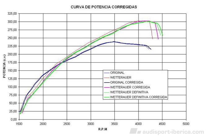
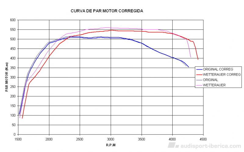
La segunda es la comparativa del par motor corrigiendo de la misma manera La tercera es la comparativa de la potencia en el motor. Hablaré con la gente de Motorsport que siempre se han portado de maravilla para que me cuenten, pero el que tengan que depender de Alemania para todo esto es un problema ya que están supeditados a lo que digan los alemanes.
-
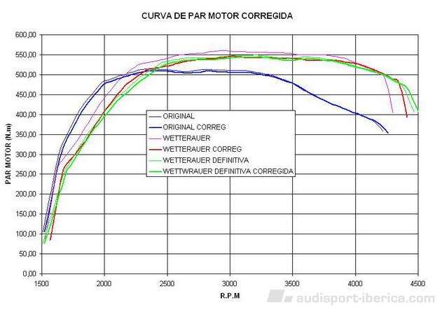
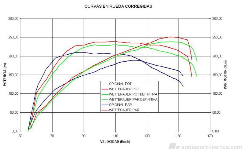
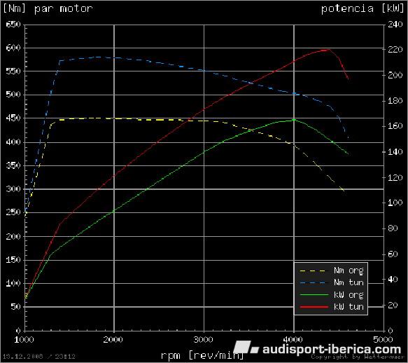
Para solucionar el problema les mandaron otra repro desde Alemania que se suponía iba a ser una intermedia y aquí os pongo la comparativa de la programación original ( la que traía el coche) la repro Wetterauer ( la 1ª que hicieron y no quedé contento) y la Wetterauer definitiva (la última que han hecho). Como se aprecia la última que han hecho es peor que la 1ª en la que no quedé contento sin embargo la sensación de conducción es diferente. El coche parece que tira desde mas abajo y el consumo se han reducido entre aprox 0,3 y 0,5 litros a los 100 km (respecto al consumo sin reprogramar). Por lo que no me explico los resultados en banco. Por otra parte lo que si que está claro es que los 580 N.m (que anuncia en la propaganda Wetterauer) que sería el par motor intermedio para que el coche no retemblara, no se consiguen. La primera grafica es la comparativa de los resultados en rueda, corrigiendo con la relación de transmisión real del coche.
-
Hola a todos, lo siento haber tardado mas de la cuenta pero después de anunciaros que colgaría los datos de la última reprogramación cuando volviera de vacaciones, han surgido problemas y ha habido que modificarla ya que el embrague no aguantaba. Conducir el coche con este par motor (630 N.m) era una gozada, salía como un cohete, pero el problema surgía entre 1800 y 2500 rpm en las que el embrague empezaba a retemblar y parecía como si estuvieras pasando por una zona rizada de baches. Como veis los datos son una pasada pero como digo el embrague no aguantaba. Me dieron la opción de cambiarlo, pero al final resultó que no existe otro embrague diferente al original para este coche. Continuo en el siguiente
-
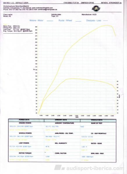
Hola a todos, al final todo se ha arreglado satisfactoriamente, la gente de MotorSportMadrid se han portado de maravilla y estuvieron un día y medio probando distintas reprogramaciones que les enviaban de Wetterauer Alemania a la vez hacían ensayos en el banco de potencia, hasta que obtuvieron el máximo. Incluso me dejaron un coche de sustitución. Ya me habían hablado bien de ellos y lo ratifico. El resultado obtenido ha sido muy bueno: 630 N.m. de par máximo a 2650 rpm y 305 cv de potencia máxima a 3800 rpm. El jueves me entregaron el coche y el viernes salí de viaje cargado hasta arriba, además de un porta-esquís con dos pares de esquís. El coche aceleraba en 6ª desde abajo (1400-1500 rpm) perfectamente y en torno a 2000 rpm. era un cohete. La sensación es que de 1500 a 2000 rpm da mas par del que aparece en las gráficas y el par máximo también parece que lo entrega antes (alrededor de 2200 rpm) . La verdad es que el coche va muy bien y recomiendo esta repro. Cuando vuelva colgaré las gráficas para que las veáis. Por cierto habría que cambiar el titulo de este post y poner “acierto Wetterauer” Saludos.
-
Gracias por el ofrecimiento, se lo diré. Saludos
-
REPRO A6 3.0 TDI WETTERAUER 300CV
jlgarce responde a jlgarce de discusión en Audi A6 / Allroad C6 (2005 - 2011)
Ya he pensado en eso. No creas que voy haciendo el loco. Conduzco de forma normal y la repro solo la hice para ganar bajos pero el resultado ha sido todo lo contrario. Como verás la zona peligrosa para el embrague ha pérdido par. Un saludo. -
REPRO A6 3.0 TDI WETTERAUER 300CV
jlgarce responde a jlgarce de discusión en Audi A6 / Allroad C6 (2005 - 2011)
Este es el enlace correcto http://www.audisport-iberica.com/foro/inde...howtopic=180193 Saludos -
REPRO A6 3.0 TDI WETTERAUER 300CV
jlgarce publicó una discusión en Audi A6 / Allroad C6 (2005 - 2011)
Hola a todos he llevado mi A6 3.0 TDI (225 cv) para hacer una repro del preparador Aleman WETTERAUER que promete 300 cv y 580 N.m de par motor y los resultados han sido decepcionantes. Para no repetir información en el foro, he colgado los detalles y datos en Preparación Audi http://www.audisport-iberica.com/foro/index.php?showforum=12 Un saludo. -
Hola a todos, hace tiempo que llevaba detrás de hacer una reprogramación a mi A6 3.0 TDI (225 cv), después de mirar mucho, la que mas me había convencido era la de OETTINGER , pero como en Madrid no había ningún preparador que la hiciera, me decidí por la de WETTERAUER a través de MotorSportMadrid que según podéis ver en la página de www.wetterauer.de se obtiene (según ellos) una potencia de 300 hp y un par de 580 N.m. Y aquí empezó la historia, llevé el coche e hicieron una prueba en banco antes y otra después de la repro (han colgado la prueba de mi coche en su página http://www.motorsportmadrid.com/index.php?id=22 y las curvas si entráis en ver todos los detalles). La verdad es que el coche dio buenos resultados antes de la repro 238 cv y 513 N.m (frente a los 225 cv y 450 N.m que declara el fabricante). Después de la repro y “aparentemente” los datos eran muy buenos 302 cv 558 N.m., aunque por debajo de los 580 N.m de par que promete WETTERAUER. Pero al probar el coche, me di cuenta que había perdido tirón abajo y acelerando en 6ª desde bajas vueltas (1500 rpm donde se supone que el coche da el par máximo de serie), le costaba mucho mas que antes salir, es decir, había perdido la alegría que tenía el coche al principio. Entonces miré con detenimiento las curvas obtenidas en banco y me di cuenta que efectivamente el coche había perdido par motor por debajo de 2300 rpm, además me di cuenta de otra cosa y es que la relación de trasmisión que habían utilizado para hacer la medición con la repro de Wetterauer (3,34) era inferior a la utilizada en la prueba anterior con el coche sin reprogramar (3,4). Luego los datos obtenidos con repro estaban falseados. Utilizando la relación de transmisión real que da el fabricante en 4ª marcha (3,43) que es en la que realizaron los ensayos, he corregido las curvas de par motor de antes y después obteniendo lo siguiente. Como veis el coche ha perdido par por debajo de 2300 rpm y el par máximo obtenido es de 545 N.m a 2900 rpm que es mucho menor del prometido 580 N.m a 2500 rpm. Todo esto lo he reclamado a MotorSportMadrid y después de dos semanas no han dado una solución al tema aunque si buenas palabras, de momento solo han quedado en concertar otro ensayo en el banco para obtener resultados reales y pedir a Wetterauer una solución. Yo personalmente no tengo claro que esto se arregle y si es así, pediré que me devuelvan el dinero y el coche a su estado original donde se mostraba mucho mas agradable de conducir que ahora, por otra parte el consumo a igualdad de conducción se ha incrementado en 1 litro. Ya iré contando….. Saludos.
-
A5 TDI multitronic 2.7 190cv VS VW Golf GT 170cv
jlgarce responde a torvic18H de discusión en Audi A5 / A5 SB 8T (2007-2016)
Siempre me han caído mal los de los Golf. Como dice ese chiste viejo : en que se parece un golf a un castillo. En que cuando se abre la puerta siempre sale un fantasma. O algo así. Ni caso y saludos. Eso si si te le encuentras por ahí machacalé.